A Beginner's Guide to Programming ESP8266 12F with Arduino IDE
Introduction: The ESP8266 12F is a versatile and cost-effective microcontroller that has gained significant popularity among hobbyists, makers, and IoT enthusiasts. Its ability to connect to Wi-Fi networks and its low cost make it an ideal choice for various projects ranging from simple IoT devices to complex home automation systems. In this article, we'll explore how to program the ESP8266 12F using the Arduino IDE, a familiar platform for many developers.
Understanding the ESP8266 12F: Before diving into programming, it's essential to understand the basics of the ESP8266 12F. This microcontroller features a powerful 32-bit processor with built-in Wi-Fi capabilities, GPIO pins for interfacing with external components, and ample memory for storing program code and data. Despite its compact size, the ESP8266 12F packs a punch, making it suitable for a wide range of applications.
Prerequisite:
- ESP8266 12F Module

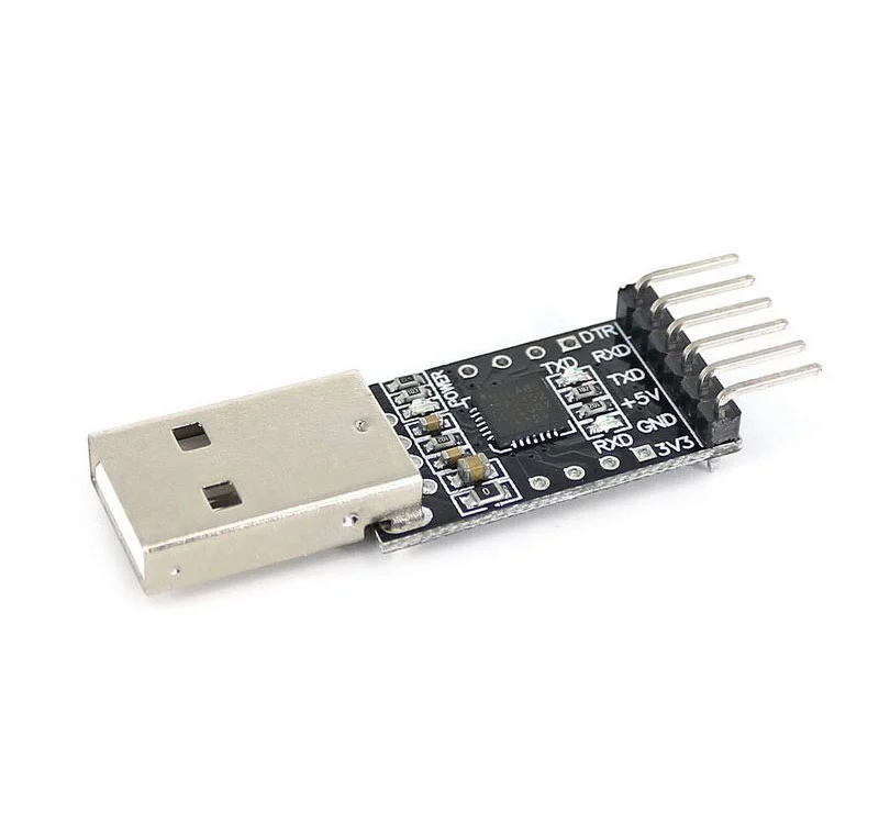
- USB to ttl converter

Setting Up the Arduino IDE: To begin programming the ESP8266 12F, you'll need to set up the Arduino IDE to support the board. Follow these steps:
- Download and install the Arduino IDE from the official website if you haven't already.
- Open the Arduino IDE and navigate to File > Preferences.
- In the "Additional Board Manager URLs" field, add the following URL: http://arduino.esp8266.com/stable/package_esp8266com_index.json
- Click "OK" to save the preferences.
- Navigate to Tools > Board > Boards Manager.
- Search for "ESP8266" and install the package.
- Once installation is complete, select the NodeMCU 1.0(ESP-12E Module) board from Tools > Board menu.
Writing Your First Program: Now that your Arduino IDE is configured for ESP8266 development, let's write a simple program to blink an LED connected to GPIO pin 2.
cppCopy code
const int LED_PIN = 2;
void setup() {
pinMode(LED_PIN, OUTPUT);
}
void loop() {
digitalWrite(LED_PIN, HIGH);
delay(1000);
digitalWrite(LED_PIN, LOW);
delay(1000);
}
This code initializes pin 2 as an output, then alternates between turning the LED on and off with one-second intervals in the main loop.
Uploading the Program: To upload the program to your ESP8266 12F board, follow these steps:
- Connect your ESP8266 12F board to your computer via USB to ttl coverter. Please follow the connection below.
ESP8266
GND -----------------------> GND
TX -----------------------> RX of USB to TTL
RX -----------------------> TX of USB to TTL
VCC ----------------------> 3.3v
EN ----------------------> 10k resistor to 3.3v
GPIO15 ----------------------> GND
GPIO0 -----------------------> to GND during uploading program.

- Select the NodeMCU 1.0(ESP-12E Module) board and port from the Tools menu.
- Click the upload button (right arrow icon) in the Arduino IDE.
- Wait for the upload process to complete.
Testing the Program: After uploading the program, you should see the LED connected to GPIO pin 2 blinking on and off at one-second intervals. This confirms that your ESP8266 12F is successfully running the program you wrote.
Conclusion: In this article, we've covered the basics of programming the ESP8266 12F using the Arduino IDE. With its powerful features and easy-to-use development environment, the ESP8266 12F opens up a world of possibilities for building IoT devices and smart systems. Whether you're a beginner or an experienced developer, experimenting with the ESP8266 12F can be both educational and rewarding. So, grab your board, fire up the Arduino IDE, and start bringing your ideas to life!
Add new comment